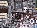
Mainboards where the BIOS chip is soldered onto the board (i.e., not in a socket) are usually problematic for coreboot developers and especially coreboot users, as one incorrectly flashed image will render the board unusable.
Here's a simple procedure how you can desolder/remove the chip from such a board, and solder on a PLCC socket instead (so that you can swap chips as often as you like later on).
Important: This will definitely void the warranty of your board! Also, we take no responsibility for any damage you inflict on your board or other stuff. Use at your own risk!
That said, we believe this procedure requires only relatively low-cost equipment which is widely available, and can also be performed by people without much soldering experience. You do not have to be a hardware/soldering guru to do any of this, with a little practice everyone can learn to perform the procedure.
Video
Uwe Hermann created a video showing most of the steps in this HOWTO. You can get it from:
- archive.org: Ogg Theora, small (32 MB), Ogg Theora (154 MB)
- Youtube: Direct download via "youtube-dl -t 'http://www.youtube.com/watch?v=30x4oxyczH4'" (FLV, 13 MB)
- blip.tv: FLV, small (20 MB)
The video is licensed under the Creative Commons Attribution-ShareAlike 3.0 license.


Requirements
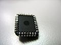
- A board with soldered-on PLCC chip (a similar procedure will likely work for DIP32 or DIP8 chips).
- A soldering iron, solder, and soldering wick.
- Optional: No Clean Flux ("Flussmitteldispenser" in German) for easier soldering.
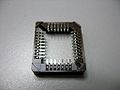
- A PLCC socket (SMD type).
- A desoldering station / heat gun (or a cutter).
- Optional: Vacuum suction pen for holding/dragging the chip.
- Optional: A special PLCC-shaped nozzle for easier desoldering.
- Tweezers.
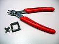
- Wire cutter.
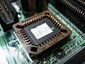
-
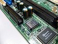
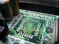
Soldered PLCC chip
-
Soldering iron
-
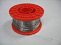
Solder
-
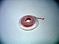
Desoldering wick
-
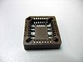
PLCC socket, front
-
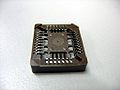
PLCC socket, back
-
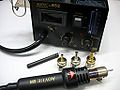
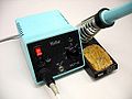
Cheap desoldering station
-
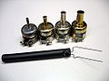
Desoldering accessories
-
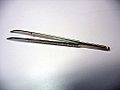
Tweezers
-
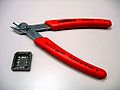
Wire cutter
-
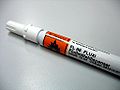
No Clean Flux


The desoldering station used here is an Aoyue 852 SMD Rework Station, which is available relatively cheaply (ca. 70.- Euros). There are even cheapers ones available, e.g. on eBay.
Preparation
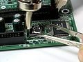
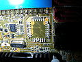
- Take a picture of the board and ROM chip. You might need that later in order to add the socket in the correct orientation. The ROM chips all have a marking where the top is (and the same is true for most boards), but on some boards there is no such marking. So write down the orientation of the chip (or take a picture).
- Prepare the PLCC socket, by cutting away the plastic middle part using the wire cutter (for easier soldering later):
-
Wire cutter and PLCC socket
-
Cut the middle part
-
Socket and removed plastic
-
Prepared socket, back side


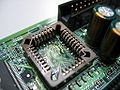
Desolder or cut away the ROM chip
The next step is to remove the soldered ROM chip. There are multiple ways to do that.
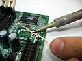
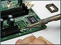
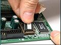
Desoldering the chip using a desoldering station
If you have access to a desoldering station use that for desoldering the chip. Use a temperature of ca. 350-370°C. Higher temperatures might speed up the process a bit, but will also increase the risk of damaging the chip or surrounding parts. At 370°C the process takes less than 20 seconds.
- Advantages:
- Quick and painless method.
- The ROM chip will usually survive, if you're careful and don't supply too much heat.
- Disadvantages:
- You have to spend some money on a desoldering station (less than 70,- Euros).
- The surrounding chips, resistors, etc. might get too hot if you're not careful (usually doesn't happen, though).
-
Soldered PLCC chip
-
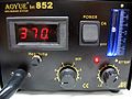
Desoldering temperature
-
Hold the chip with tweezers
-
Desoldering the chip
-
PCB pads after desoldering
-
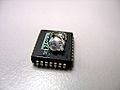
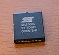
Desoldered chip, front
-
Desoldered chip, back


Desoldering the chip using a heat gun and aluminum foil
You can also use a piece of aluminum foil and a house hold heat gun for desoldering the chip. Most heat guns have a high and low setting, you will only need the low setting. The whole process only takes a few minutes. Blow the heat at an angle to the side of the chip at the solder joints going around the chip in a circle (never directly on top).
- Advantages:
- Fairly quick and painless as long as you don't burn yourself.
- The ROM chip will usually survive, if you're careful and don't supply too much heat.
- Disadvantages:
- You have to be very careful not to pull on the chip. You could lift a solder pad causing a whole other issue.
- The foil can get pretty hot!
-
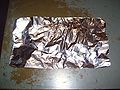
Aluminum foil folded in half (double protection).
-
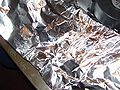
Bend the foil over the chip for cut out lines.
-
Cut out a chip-sized rectangle.
-

Foil with chip cut out.
-
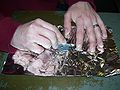
Place the foil over the chip.
-
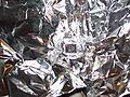
Close up of foil over chip.
-
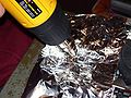
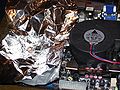
Blow the heat at an angle to the chip's side.
-
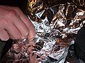
Soon the chip will fall off. Use tweezers to remove.
-
Foil and chip removed.
-

Foil and chip.
-
Clean the pads, solder on the socket.


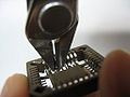
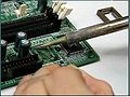
Cutting the chip
Alternatively, you can just cut away the chip with a proper cutter (e.g. the Hakko CHP Ergonomic Micro Cutter). Make sure to cut as close to the packaging as possible, so as to minimize strain on the paths on the motherboard while the chip is being cut off.
- Advantages:
- No desoldering station required.
- Surrounding chips, capacitors, etc. are not at risk from a heat gun.
- Disadvantages:
- Cutting the chip is a bit tedious.
- The chip is rendered unusable in the process (so make sure you have a backup before cutting it).
-
Legs cut off on two sides.
-
Chip removed. Only the legs remain.
-
The PLCC chip with the legs cut off.


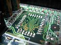
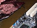
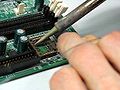
Clean the pads on the board
The next step is to clean the PCB pads, i.e., remove the remains of solder from the pads. Use desoldering wick for that.
-
Pads before cleaning
-
Cleaning with desoldering wick
-
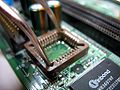
Cleaned pads


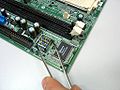
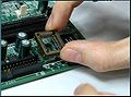
Solder the socket onto the board
Now solder the PLCC socket onto the pads. This procedure is best performed manually with a soldering iron (in theory you could try to use a desoldering station / heat gut, but the results are probably not too good, and you might melt the plastic socket). Optionally, if you have some No Clean Flux handy, apply some of it on the pads. This will make the soldering process a bit easier.
We suggest to start by aligning the socket onto the pads with tweezers or with your fingers. Solder two pins in opposite corners of the socket first, in order to fixate the socket. Then solder all the other pins, one after the other. If you apply too much solder and two or more pins get connected accidentally, use the soldering wick to fix that.
-
Put solder on a pad
-
Put solder on another pad
-
Aligning, tweezers
-
Aligning, fingers
-
Soldering the socket
-
Soldered-on socket
-
Testing the socket
-
Socket with chip


Tips
To keep your ROM chip from pushing in too far and possibly touching the wrong solder joint, you can use a small piece of single sided adhesive felt or thin foam. Cut out a small rectangle just big enough to fit into the opening of your PLCC Socket and stick it in the bottom of the socket against the PCB. Another tip is to place a small drop of super glue on each corner of the outside of the PLCC Socket. This helps your newly installed socket from lifting (causing damage to the solder pads) when you remove the ROM chip, which is a good idea if you are swapping out your ROM chip frequently.
Results
Congratulations. You have now successfully replaced a soldered-on PLCC ROM chip on your board with a PLCC socket. You can now swap out the ROM chip as often as you want to or need to. In almost all cases, the board and the ROM chip will survive this procedure if you are careful.
Further resources
- HOWO: replace a PLCC chip with a socket "ghetto style" (tutorial for doing this without desoldering station by cutting the chip)
- Coreboot hacking: How to solder a PLCC socket on your board (blog post)
| I, the copyright holder of this work, hereby release it into the public domain. This applies worldwide.
In case this is not legally possible: |